The method is also called E.M.F. method of determining the regulation. The method requires following data to calculate the regulation.
1. The armature resistance per phase (Ra).
2. Open circuit characteristics which is the graph of open circuit voltage against the field current. This is possible by conducting open circuit test on the alternator.
3. Short circuit characteristics which is the graph of short circuit current against field current. This is possible by conducting short circuit test on the alternator.
Let us see, the circuit diagram to perform open circuit as well as short circuit test on the alternator. The alternator is coupled to a prime mover capable of driving the alternator at its synchronous speed. The armature is connected to the terminals of a switch. The other terminals of the switch are short circuited through an ammeter. The voltmeter is connected across the lines to measure the open circuit voltage of the alternator.
The field winding is connected to a suitable d.c. supply with rheostat connected in series. The field excitation i.e. field current can be varied with the help of this rheostat. The circuit diagram is shown in the Fig. 1.
 |
| Fig. 1 Circuit diagram for open circuit and short circuit test on alternator |
1.1 Open Circuit Test
Procedure to conduct this test is as follows :
i) Start the prime mover and adjust the speed to the synchronous speed of the alternator.
ii) Keeping rheostat in the field circuit maximum, switch on the d.c. supply.
iii) The T.P.S.T switch in the armature circuit is kept open.
iv) With the help of rheostat, field current is varied from its minimum value to the rated value. Due to this, flux increasing the induced e.m.f. Hence voltmeter reading, which is measuring line value of open circuit voltage increases. For various values of field current, voltmeter readings are observed.
The observation for open circuit test are tabulated as below :
Observation table for open circuit test :

From the above table, graph of (Voc)ph against If is plotted.
Note : This is called open circuit characteristics of the alternator, called O.C.C. This is shown in the Fig. 2.
 |
| Fig. 2 O.C.C. and S.C.C. of an alternator |
1.2 Short Circuit Test
After completing the open circuit test observation, the field rheostat is brought to maximum position, reducing field current to a minimum value. The T.P.S.T switch is closed. As ammeter has negligible resistance, the armature gets short circuited. Then the field excitation is gradually increased till full load current is obtained through armature winding. This can be observed on the ammeter connected in the armature circuit. The graph of short circuit armature current against field current is plotted from the observation table of short circuit test. This graph is called short circuit characteristics, S.C.C. This is also shown in the Fig. 2.
Observation table for short circuit test :

The S.C.C. is a straight line graph passing through the origin while O.C.C. resembles B-H curve of a magnetic material.
Note : As S.C.C. is straight line graph, only one reading corresponding to full load armature current along with the origin is sufficient to draw the straight line.
1.3 Determination of From O.C.C. and S.C.C.
The synchronous impedance of the alternator changes as load condition changes. O.C.C. and S.C.C. can be used to determine Zs for any load and load p.f. conditions.
In short circuit test, external load impedance is zero. The short circuit armature current is circulated against the impedance of the armature winding which is Zs. The voltage responsible for driving this short circuit current is internally induced e.m.f. This can be shown in the equivalent circuit drawn in the Fig. 3.
 |
| Fig. 3 Equivalent circuit on short circuit |
Zs = Eph/ Iasc
Now value of Iasc is known, which can observed on the alternator. But internally induced e.m.f. can not be observed under short circuit condition. The voltmeter connected will read zero which is voltage across short circuit. To determine Zs it is necessary to determine value of E which is driving Iasc against Zs.
Now internally induced e.m.f. is proportional to the flux i.e. field current If.Eph α Φ α If ...... from e.m.f. equation
So if the terminal of the alternator are opened without disturbing If which was present at the time of short circuited condition, internally induced e.m.f. will remain same as Eph. But now current will be zero. Under this condition equivalent circuit will become as shown in the Fig. 4.
 |
| Fig. 4 |
It is clear now from the equivalent circuit that as Ia = 0 the voltmeter reading (Voc)ph will be equal to internally induced e.m.f. (Eph).
This is what we are interested in obtaining to calculate value of Zs. So expression for Zs can be modified as,

The value of Zs is different for different values of If as the graph of O.C.C. is non linear in nature.
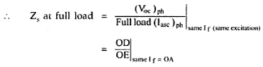
So suppose Zs at full load is required then,
Iasc = full load current.
From S.C.C. determine If required to drive this full load short circuit Ia. This is equal to 'OA', as shown in the Fig.2.
Now for this value of If, (Voc)ph can be obtained from O.C.C. Extend kine from point A, till it meets O.C.C. at point C. The corresponding (Voc)ph value is available at point D.
(Voc)ph = ODWhile (Iasc)ph = OE
General steps to determine Zs at any load condition are :
i) Determine the value of (Iasc)ph for corresponding load condition. This can be determined from known full load current of the alternator. For half load, it is half of the full load value and so on.
ii) S.C.C. gives relation between (Iasc)ph and If. So for (Iasc)ph required, determine the corresponding value of If from S.C.C.
iii) Now for this same value of If, extend the line on O.C.C. to get the value of (Voc)ph. This is (Voc)ph for same If, required to drive the selected (Iasc)ph.
iv) The ratio of (Voc)ph and (Iasc)ph, for the same excitation gives the value of Zs at any load conditions.The graph of synchronous impedance against excitation current is also shown in the Fig. 2.
1.4 Regulation Calculations
From O.C.C. and S.C.C., Zs can be determined for any load condition.
The armature resistance per phase (Ra) can be measured by different methods. One of the method is applying d.c. known voltage across the two terminals and measuring current. So value of Ra per phase is known.

No load induced e.m.f. per phase, Eph can be determined by the mathematical expression derived earlier.
Ia = Phase value of current depending on the load condition
cosΦ = p.f. of load
Positive sign for lagging power factor while negative sign for leading power factor, Ra and Xs values are known from the various tests performed.
The regulation then can be determined by using formula,
1.5 Advantages and Limitations of Synchronous Impedance Method
The main advantages of this method is the value of synchronous impedance Zsfor any load condition can be calculated. Hence regulation of the alternator at any load condition and load power factor can be determined. Actual load need not be connected to the alternator and hence method can be used for very high capacity alternators.
The main limitation of this method is that the method gives large values of synchronous reactance. This leads to high values of percentage regulation than the actual results. Hence this method is called pessimistic method.
can u pls give me a hint how much matter could i writr in an exam
ReplyDeleteAccording to marks alloted to the question, you need to write the answer
Delete