Translate

Showing posts with label Single Phase Induction motor. Show all posts

Friday, July 12, 2013

Conducts Tests on Single Phase Induction Motor

Similar to a three phase induction motor, the various tests can be performed on single phase induction motor. The results of these tests can be used to obtain the equivalent circuit parameters of a single phase induction motor. The tests usually conducted are :
1. No load test or open circuit test
2. Blocked rotor test or short circuit test

1. No load test
       The test is conducted by rotating the motor without load. The input current, voltage and power are measured by connecting the ammeter, voltmeter and wattmeter in the circuit. These readings are denoted as V, Iand W.
Now                 W= VIcosΦ

       The motor speed on no load is almost equal to its synchronous speed hence for practical purposes, the slip can be assumed zero. Hence r2/s becomes ∞ and acts as open circuit in the equivalent circuit. Hence for forward rotor circuit, the branch r2/s + j x2 gets eliminated.
       While for a backward rotor circuit, the term r2/(2 - s) tends to r2/2. Thus xis much higher then the impedance r2/2 + j x2. Hence it can be assumed that no current can flow through and that branch can be eliminated.
       So circuit reduces to as shown in the Fig.1.
Fig. 1

       Now the voltage across xis VAB 
But                    VAB = Ix
...                       x= VAB /I
But                   x= X/2
   
       Thus magnetising reactance Xcan be determined.
       The no load power Wis nothing but the rotational losses.

2. Blocked Rotor Test
       In balanced rotor test, the rotor is held fixed so that it will not rotate. A reduced voltage is applied to limit the short circuit current. This voltage is adjusted with the help of autotransformer so that the rated current flows through main winding. The input voltage, current and power are measured by connecting voltmeter, ammeter and wattmeter respectively. These readings are denoted as Vsc , Isc and Wsc.
       Now as rotor is blocked, the slip s = 1 hence the magnetising reactance xis much higher than the rotor impedance and hence it can be neglected as connected in parallel with the rotor. Thus the equivalent circuit for blocked rotor test is as shown in the Fig.2.
Fig. 2

                     Wsc = Vsc Isc cos Φsc
                      cos Φsc =Wsc /Vsc Isc 
                                 = blocked rotor power factor
Now               Zeq = Vsc/ Isc
                       Req = Wsc /( Isc)2 
But                  Req = R+ R
 ...                     R= Req - R
                          = rotor resistance referred to stator
                         Xeq =√(Zeq 2 - Req 2)
                         X=  X2  we get,

       The stator resistance is measured by voltmeter-ammeter method, by disconnecting the auxiliary winding and capacitors present if any. Due to skin effect, the a.c. resistance is 1.2 to 1.5 times more than the d.c. resistance.
       Key point : Thus with two tests, all the parameters of single phase induction motor can be obtained.

Equivalent Circuit of Single Phase Induction Motor

The double revolving field theory can be effectively used to obtain the equivalent circuit of a single phase induction motor. The method consists of determining the values of both the fields clockwise and anticlockwise at any given slip. When the two fields are known, the torque produced by each can be obtained. The difference between these two torques is the net torque acting on the rotor.
       Imagine the single phase induction motor is made up of one stator winding and two imaginary rotor windings. One rotor is rotating in forward direction i.e. in the direction of rotating magnetic field with slip s while other is rotating in backward direction i.e. in direction of oppositely directed rotating magnetic field with slip 2 - s.
       To develop the equivalent circuit, let us assume initially that the core loss is absent.
1. Without core loss
Let the stator impedance be Z Ω
                            Z = R1 + j X1
Where                  R1 = Stator resistance
                             X= Stator reactance
And                      X = rotor reactance referred to stator
                             R2 = rotor resistance referred to stator
       Hence the impedance of each rotor is r2 + j x2   where
                            x2 = X2/2
       The resistance of forward field rotor is r2/s while the resistance of backward field rotor is r2 /(2 - s). The r2 value is half of the actual rotor resistance referred to stator.
       As the core loss is neglected, Ro is not existing in the equivalent circuit. The xo is half of the actual magnetising reactance of the motor. So the equivalent circuit referred to stator is shown in the Fig.1.
Fig. 1  Equivalent circuit without core loss
       Now the impedance of the forward field rotor is Zf  which is parallel combination of  (0 + j xo ) and (r2 /s) + j x2
 
        While the impedance of the backward field rotor is Zwhich is parallel combination of  (0 + j xo) and (r2 / 2-s) + j x2.
       Under standstill condition, s = 1 and 2 - s = 1 hence Zf  = Zb  and hence V= V. But in the running condition, Vf  becomes almost 90 to 95% of the applied voltage.
...                           Zeq  = Z1  + Zf  + Z  = Equivalent impedance
Let                         I2f  = Current through forward rotor referred to stator
and                         I2b  = Current through backward rotor referred to stator
...                            I2f  = /((r2/s) + j x2) where Vf  = I1  x Zf  
and                         I2b  = /((r2/2-s)  + j x2)
                               Pf  = Power input to forward field rotor
                                   = (I2f)2 (r2/s)  watts
                               P= Power input to backward field rotor
                                    = (I2b)2 (r2/2-s) watts
                              Pm  = (1 - s){ Net power input} 
                                    = (1 - s) (Pf  - P) watts
                              Pout = P- mechanical loss - core loss
...                           Tf  = forward torque = P/(2πN/60) N-m
and                        Tb = backward torque = P/(2πN/60) N-m
                               T = net torque = Tf  - Tb  
while                       Tsh  = shaft torque = Pout /(2πN/60) N-m
                              %η = (net output / net input) x 100

2. With core loss
       If the core loss is to be considered then it is necessary to connect a resistance in parallel with, in an exciting branch of each rotor is half the value of actual core loss resistance. Thus the equivalent circuit with core loss can be shown as in the Fig. 2.
Fig. 2 Equivalent circuit with core loss

Let                    Zof  = Equivalent impedance of exciting branch in forward rotor
                              = ro║(j xo )
and                     Zob  = Equivalent impedance of exciting branch in backward rotor
                                  = ro║(j xo )
...                          Zf  = Zof  ║( r2/s + j x2 )
       All other expressions remains same as stated earlier in case of equivalent circuit without core loss.

Shaded Pole Induction Motor

This type of motor consists of a squirrel cage rotor and stator consisting of salient poles i.e. projected poles. The poles are shaded i.e. each pole carries a copper band on one of its unequally divided part called shading ban Fig.1(a) shows 4 pole shaded pole construction while Fig. 1(b) shows a single pole consisting of copper shading band.

Fig 1

Key point : When single phase a.c. supply is given to the stator winding, due to shading provided to the poles, a rotating magnetic field is generated.
       The production of rotating magnetic field can be explained as below : 
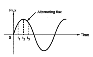
       The current carried by the stator winding is alternating and produces alternating flux. The waveform of the flux is shown in the Fig. 2(a). The distribution of this flux in the pole area is greatly influenced by the role of copper shading band. Consider the three instants say t1, t2 and  t3 during first half cycle of the flux as shown, in the Fig 2(a).
Fig. 2 (a)  Waveform of stator flux
       At instant t = t1, rate of rise of current and hence the flux is very high. Due to the transformer action, large e.m.f. gets induced in the copper shading band. This circulates current through shading band as it is short circuited, producing its own flux. According to lenz's law, the direction of this current is so as to oppose the cause i.e. rise in current. Hence shading ring flux is opposing to the main flux. Hence there is crowding of flux in nonshaded part while weakening of flux in shaded part. Overall magnetic axis shifts in nonshaded part as shown in the Fig. 2(b).
Fig. 2  Production of rotating magnetic field
        At instant t = t2, rate of rise of current and hence the rate of change of flux is almost zero as flux almost reaches to its maximum value. So dΦ/dt = 0. Hence there is very little induced e.m.f. in the shading ring. Hence the shading ring flux is also negligible, hardly affecting the distribution of the main flux. Hence the main flux distribution is uniform and magnetic axis lies at the centre of the pole face as shown in the Fig. 2(c).
        At the instant t = t3, the current and the flux is decreasing. The rate of decrease is high which again induces a very large e.m.f. in the shading ring. This circulates current through the ring which produces its own flux. Now direction of the flux produced by the shaded ring current is so as to oppose the cause which is decrease in flux. So it oppose the decrease in flux means its direction is same as that of main flux, strengthening it. So there is crowding of flux in the shaded part as compared to nonshaded part. Due to this the magnetic axis shifts to the middle of the shaded part of the pole. This is shown in the Fig. 2(d).
       This sequence keeps on repeating for negative half cycle too. Consequently this produces an effect of rotating magnetic field, the direction of which is from nonshaded part of the pole to the shaded part of the pole. Due to this, motor produces the starting torque is low which is about 40 to 50% of the full load torque for this type of motor. The torque speed characteristics is shown in the Fig. 3.
Fig. 3  Torque-speed characteristics of shaded pole motor
       Due to absence of centrifugal switch the construction is simple and robust but this type of motor has a lot of lamination as :
  1. The starting torque is poor.
  2. The power factor is very low.
  3. Due to I2R, copper losses in the shading ring the efficiency is very low.
  4. The speed reversal is very difficult. To achieve the speed reversal, the additional set of shading rings is required. By opening one set and closing other, direction can be reversed but the method is complicated and expensive.
  5.  The size and power rating of these motors is very small. These motors are usually available in a range of 1/300 to 1/20 kW.
Application
        These motors are cheap but have very low starting torque, low power factor and low efficiency. These motors are commonly used for the small fans, by motors, advertising displays, film projectors, record players, gramophones, hair dryers, photo copying machines etc.

Capacitor Start Induction Motors

The construction of this type of motors is similar to the resistance split phase type. The difference is that in series with the auxiliary winding the capacitor is connected. The capacitive circuit draws a leading current, this feature used in this type to increase the split phase angle α between the two currents Im and Ist.
       Depending upon whether capacitor remains in the circuit permanently or is disconnected from the circuit using centrifugal switch, these motors are classified as, 
1. Capacitor start motor and       2. Capacitor start capacitor run motors
        The connection of capacitor start motor is shown in the Fig. 1(a). The current Imlags the voltage by angle Φm while due to capacitor the current Ist leads the voltage by angleΦst. Hence there exists a large phase difference between the two currents which is almost 90, which is an ideal case. The phasor diagram is shown in the Fig.1(b).
Fig 1.  Capacitor start motor

       The starting torque is proportional to 'α 'and hence such motors produce very high starting torque .
       When speed approaches to 75 to 80% of the synchronous speed, the starting winding gets disconnected due to operation of the centrifugal switch. The capacitor remains in the circuit only at start hence it is called capacitor start motors.
Key point : In case of capacitor start capacitor run motor, there is no centrifugal switch and capacitor remain permanently in the circuit. This improves the power factor.
       The schematic representation of such motor is shown in the Fig. 2.
Fig. 2 Capacitor start capacitor run motor

       The phasor diagram remains same as shown in the Fig.1(b). The performance not only at start but in running condition also depends on the capacitor C hence its value is to be designed so as to compromise between best starting and best running condition. Hence the starting torque available in such type of motor is about 50 to 100% of full load torque.
       The direction of rotation, in both the types can be changed by interchanging the connection of main winding or auxiliary winding. The capacitor permanently in the circuit improves the power factor. These motors are more costly than split phase type motors.
       The capacitor value can be selected as per the requirement of starting torque, the starting torque can be as high as 350 to 400 % of full load torque. The torque-speed characteristics is as shown in the Fig.3.
Fig.3  Torque speed characteristic of capacitor split phase motor

Applications 
       These motors have high starting torque and hence are used for hard starting loads. These are used for compressors, conveyors, grinders, fans, blowers, refrigerators, air conditions etc. These are most commonly used motors. The capacitor start capacitor run motors are used in celling fans, blowers and air-circulations. These motors are available upto 6 kW.


Example : A 250 W, 230 V, 50 Hz capacitor start motor has the following impedances at standstill.
Main winding, Zm = 7 + j5 Ω
Auxiliary winding, Za = 11.5 + j5 Ω
       Find the value of capacitor to be connected in series with the auxiliary winding to give a phase displacement of  between the currents in two windings. Draw the circuit and phasor diagram for motor.

Solution : Let Xc be the capacitive reactance to be connected with auxiliary winding at start, as shown in the Fig. 1(a).
Fig. 1(a)

...              Za = 11.5 + j (5-Xc ) Ω
                     = 7 + j5 Ω = 8.6023
       Now  Ia and Im must have a phase difference of 90o.  Im will lag the voltage by 35.5376hence Ia must lead the voltage by (90o- 35.5376) i.e. 53.4624, as shown in the Fig 1(b).
Fig. 1(b)

       The phase angle of  Za is, 
                   Φa =tan-1((5 - Xc )/11.5) = -53.4624
Key point :As leads, the phase angle of i.e. must be negative hence taken as 
                   tan(-53.4624) = (5 - Xc )/11.5 i.e.
                   -1.34956 = (5 - Xc )/11.5
..                  Xc = 20.52 Ω = 1/(2πfC)
..                  C = 1/(2π x 50 x 20.52) = 155.1217 μF

Split Phase Induction Motor

This type of motor has single phase stator winding called main winding. In addition to this, stator carries one more winding called auxiliary winding or starting winding. The auxiliary winding carries a series resistance such that its impedance is highly resistive in nature. The main winding is inductive in nature.

                   Let                  Im = Current through main winding 
                   and                  Ist = Current through auxiliary winding

       As main winding is inductive, current Im lags voltage by V by a large angle Φmwhile Ist is almost in phase in V as auxiliary winding is highly resistive. Thus three exists a phase difference of α between the two currents and hence between the two fluxes produced by the two currents. This is shown in the Fig.1(c). The resultant of these two fluxes is a rotating magnetic field. Due to this, the starting torque, which acts only in one direction is produced.
Fig. 1   Split phase induction motor

       The auxiliary winding has a centrifugal switch in series with it. When motor gather a speed upto 75 to 80% of the synchronous speed, centrifugal switch gets opened mechanically and in running condition auxiliary winding remains out of the circuit. So motor runs only stator winding. So auxiliary winding is designed for short time use while the main winding is designed for continuous use. As the current Imand are splitted from each other by angle 'α ' at start, the motor is commonly called split phase motor.
       The torque-speed characteristics of split phase motors is shown in the Fig.2.
Fig.  2

       The starting torque Tst is proportional to the split angle 'α ' but split phase motors give poor starting torque which is 125 to 150% of full load torque.
        The direction of rotation of this motor can be reversed by reversing the terminals of either main winding or auxiliary winding. This changes the direction of rotating magnetic field which in turn changes the direction of rotation of the motor.

Applications
       These motors have low starting current and moderate starting torque. These are used for easily started loads like fans, blowers, grinders, centrifugal pumps, washing machines, oil burners, office equipments etc. These are available in the range of 1/120 to 1/2 kW.

Types of Single Phase Induction Motors

 In practice some arrangement is provided in the single phase induction motors so as that the stator flux produced becomes rotating type rather than the alternating type, which rotates in particular direction only. So torque produced due to such rotating magnetic field is unidirectional as there is no oppositely directed torque present. Hence under the influence of rotating magnetic field in one direction, the induction motor becomes self starting. It rotates in same direction as that of rotating magnetic field. Thus depending upon the methods of producing rotating stator magnetic flux, the single phase induction motors are classified as,
  1. Split phase induction motor
  2. Capacitor start induction motor
  3. Capacitor start capacitor run induction motor
  4. Shaded pole induction motor
        To produce rotating magnetic field, it is necessary to have minimum two alternating fluxes having a phase difference between the two. The interaction of such two fluxes produces a resultant flux which is rotating magnetic flux, rotating in space in one particular direction. So an attempt is made in all the single phase induction motors to produce an additional flux other than stator flux, which has a certain phase difference with respect to stator flux.
        Such two fluxes are shown in the Fig. 1 having phase difference of between them.
Fig. 1
       More the phase difference angle α, more is starting torque produced. Thus production of rotating magnetic field at start is important to make the single phase induction motors self starting. Once the motor starts, then another flux Φ2 may be removed and motor can continue to rotate under influence of stator flux or main flux alone.
       Let us see how the rotating magnetic field is produced in various types of single phase induction motors.