Showing posts with label Synchronous motor. Show all posts
Showing posts with label Synchronous motor. Show all posts
Friday, July 12, 2013


Applications of Three Phase Synchronous Motor
The important characteristics of the synchronous motor is its constant speed irrespective of the load conditions, and variable power factor operation. As seen earlier its power factor can be controlled by controlling its excitation. For overexcitation its power factor is leading in nature, which is very important from the power factor correction point of view.
Due to constant speed characteristics, it is used in machine tools, motor generator sets, synchronous clocks, stroboscopic devices, timing devices, belt driven reciprocating compressors, fans and blowers, centrifugal pumps, vacuum pumps, pulp grinders, textile mills, paper mills line shafts, rolling mills, cement mills etc.
The synchronous motors are often used as a power factor correction device, phase advancers and phase modifiers for voltage regulation of the transmission lines. This is possible because the excitation of the synchronous motor can be adjusted as per the requirement.
The disadvantages of synchronous motor are their higher cost, necessity of frequent maintenance and a need of d.c. excitation source, auxiliary device or additional winding provision to make it self starting. Overall their initial cost is very high.
Synchronous Condensers
When synchronous motor is over excited it takes leading p.f. current. If synchronous motor is on no load, where load angle δ is very small and it is over excited (Eb > V) then power factor angle increases almost upto 90o. And motor runs with almost zero leading power factor condition. This is shown in the phasor diagram Fig. 1.
 |
| Fig. 1 Synchronous condenser |
This characteristics is similar to a normal capacitor which takes leading power factor current. Hence over excited synchronous motor operating on no load condition is called as synchronous condenser or synchronous capacitor. This is the property due to which synchronous motor is used as a phase advancer or as power improvement device.
Synchronization With Infinite Bus Bar
There is a specific procedure of connecting synchronous machine to infinite bus bars. Infinite bus bar is one which keeps constant voltage and frequency although load varies. The Fig. 1 shows a synchronous machine which is to be connected to the bus bars with the help of switch K.
If the synchronous machine is running as a generator then its phase sequence should be some as that of bus bars. The machine speed and field current is adjusted in such a way so as to have the machine voltage same as that of bus bar voltage. The machine frequency should be nearly equal to bus bar frequency so that the machine speed is nearer to synchronous speed.
 |
| Fig. 1 |
When the above conditions are satisfied, the instant of switching for synchronization should be determined. This can be determined by lamps dark method, Lamps bright and dark method or by using synchroscope.
Hunting in Synchronous Motor
It is seen that, when synchronous motor is on no load, the stator and rotor pole axes almost coincide with each other.
When motor is loaded, the rotor axis falls back with respect to stator. The angle by which rotor retards is called load angle or angle of retardation δ.
If the load connected to the motor is suddenly changed by a large amount, then rotor tries to retard to take its new equilibrium position.
But due to inertia of the rotor, it can not achieve its final position instantaneously. While achieving its new position due to inertia it passes beyond its final position corresponding to new load. This will produce more torque than what is demanded. This will try reduce the load angle and rotor swings in other direction. So there is periodic swinging of the rotor on both sides of the new equilibrium position, corresponding to the load. Such a swing is shown in the Fig. 1.
 |
| Fig. 1 Hunting in synchronous motor |
Such oscillations of the rotor about its new equilibrium position, due to sudden application or removal of load is called swinging or hunting in synchronous motor.
Salient Pole Synchronous Motor
The analysis of salient pole synchronous motor is based on the Blondel's two reaction. The direct and quadrature axis components of current and reactance are same as defined earlier for the synchronous generators. Thus,
Xd = Direct axis reactance
Xq = Quadrature axis reactance
Id = Direct axis component of Ia
Iq = Quadrature axis component of Ia
The complete phasor diagram of lagging p.f. is shown in the Fig. 1.
 |
| Fig. 1 Phasor diagram for lagging p.f. |
From the phasor diagram it can be derived that,

Note : For the proof of above results refer example 2.
The complete phasor diagram of leading p.f. is shown in the Fig. 2.
 |
| Fig. 2 Phasor diagram for leading p.f. |
For this leading p.f. case,
Note : Φ should be taken negative for the leading power factor for calculating other parameters.
While the mechanical power developed per phase is given by,
Total Pm = 3 x Pm

Blondel Diagram { Constant Power Circle)
The Blondel diagram of a synchronous motor is an extension of a simple phasor diagram of a synchronous motor.
For a synchronous motor, the power input to the motor per phase is given by,
Pin = Vph Iph cosΦ ............ per phase
The gross mechanical power developed per phase will be equal to the difference between Pin per phase and the per phase copper losses of the winding.
Copper loss per phase = (Iaph)2 Ra
... Pm = Vph Iph cosΦ - (Iaph)2 Ra .......... per phase
For mathematical convenience let Vph = V and Iaph = I,
... Pm = VI cos - I2 Ra
... I2 Ra - VI cos + Pm = 0

Now consider the phasor diagram as shown in the Fig. 1.
 |
| Fig. 1 |
The equation (1) represents polar equation to a circle. To obtain this circle in a phasor diagram, draw a line OY at an angle θ with respect to OA.
 |
| Fig. 2 Blondel diagram |
The circle represented by equation (1) has a centre at some point O' on the line OY. The circle drawn with centre as O' and radius as O'B represents circle of constant power. This is called Blondel diagram, shown in the Fig. 2.
Thus if excitation is varied while the power is kept constant, then working point B while move along the circle of constant power.
Let O'B = Radius of circle = r
OO' = Distant d
Applying cosine rule to triangle OBO',

Now OB represents resultant ER which is Ia Zs. Thus OB is proportional to current and when referred to OY represents the current in both magnitude and phase.
OB = Ia = I say
Substituting various values in equation (2) we get,
r2 = I2 + d2 - 2dI cosΦ

Comparing equations (1) and (3) we get,

Thus the point O' is independent of power Pm and is a constant for a give motor operating at a fixed applied voltage V.
Comparing last term of equations (1) and (3),

The equation shows that as power Pm must be real, then 4Pm Ra ≥ V2 . The maximum possible power per phase is,

And the radius of the circle for maximum power is zero. Thus at the time of maximum power, the circles becomes a point O'.
While when the power Pm = O, then
r = V/2Ra = OO'
This shows that the circle of zero power passes through the points O and A.
The radius for any power Pm is given by,

This is generalised expression for the radius for any power.
Condition for Maximum Power Developed
The value of δ for which the mechanical power developed is maximum can be obtained as,

Note : Thus when Ra is negligible, θ = 90o for maximum power developed. The corresponding torque is called pull out torque.
1.1 The Value of Maximum Power Developed
The value of maximum power developed can be obtained by substituting θ =δ in the equation of Pm.
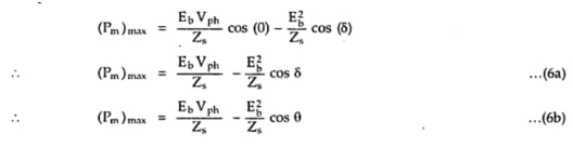 When Ra is negligible, θ = 90o and cos (θ) = 0 hence,

... Ra = Zs cosθ and Xs = Zs sinθ
Substituting cosθ = Ra/Zs in equation (6b) we get,
 Solving the above quadratic in Eb we get,

As Eb is completely dependent on excitation, the equation (8) gives the excitation limits for any load for a synchronous motor. If the excitation exceeds this limit, the motor falls out of step.
1.2 Condition for Excitation When Motor Develops (Pm ) Rmax
Let us find excitation condition for maximum power developed. The excitation controls Eb. Hence the condition of excitation can be obtained as,


Note : Note that this is not maximum value of but this is the value of foe which power developed is maximum.
The corresponding value of maximum power is,

Alternative Expression for Power Developed by a Synchronous Motor
Consider the phasor diagram of a synchronous motor running on leading power factor cosΦ as shown in the Fig. 1.
 |
| Fig. 1 |
The line CD is drawn at an angle θ to AB.
The lines AC and DE are perpendicular to CD and AE.

and angle between AB = Ebph and Iaph is also ψ.
Power Flow in Synchronous Motor
Net input to the synchronous motor is the three phase input to the stator.
... Pin = √3 VL IL cosΦ W
where VL = Applied Line Voltage
IL = Line current drawn by the motor
cosΦ = operating p.f. of synchronous motor
or Pin = 3 ([er phase power)
= 3 x Vph Iaph cosΦ W
Now in stator, due to its resistance Ra per phase there are stator copper losses.
Total stator copper losses = 3 x (Iaph)2 x Ra W
Now P = T x ω
... Pm = Tg x (2πNs/60) as speed is always Ns

Total stator copper losses = 3 x (Iaph)2 x Ra W
... The remaining power is converted to the mechanical power, called gross mechanical power developed by the motor denoted as Pm.
... Pm = Pin - Stator copper lossesNow P = T x ω
... Pm = Tg x (2πNs/60) as speed is always Ns

Expression for Back E.M.F or Induced E.M.F. per Phase in S.M.
Case i) Under excitation, Ebph < Vph .
Zs = Ra + j Xs = | Zs | ∟θ Ω
θ = tan-1(Xs/Ra)
ERph ^ Iaph = θ, Ia lags always by angle θ.
Vph = Phase voltage applied
ERph = Back e.m.f. induced per phase
ERph = Ia x Zs V ... per phase
Let p.f. be cosΦ, lagging as under excited,
Vph ^ Iaph = Φ
Phasor diagram is shown in the Fig. 1.
 |
| Fig. 1 Phasor diagram for under excited condition |
Applying cosine rule to Δ OAB,
(Ebph)2 = (Vph)2 + (ERph)2 - 2Vph ERph x (Vph ^ ERph)
but Vph ^ ERph = x = θ - Φ
(Ebph)2 = (Vph)2 + (ERph)2 - 2Vph ERph x (θ - Φ) ......(1)
where ERph = Iaph x Zs
Applying sine rule to Δ OAB,
Ebph/sinx = ERph/sinδ

So once Ebph is calculated, load angle δ can be determined by using sine rule.
Case ii) Over excitation, Ebph > Vph
p.f. is leading in nature.
ERph ^ Iaph = θ
Vph ^ Iaph = Φ
The phasor diagram is shown in the Fig. 2.
 |
| Fig.2 Phasor diagram for overexcited condition |
Applying cosine rule to Δ OAB,
(Ebph)2 = (Vph)2 + (ERph)2 - 2Vph ERph x cos(Vph ^ ERph)
Vph ^ ERph = θ + Φ
... (Ebph)2 = (Vph)2 + (ERph)2 - 2 Vph ERph cos(θ + Φ) .......(3)
But θ + Φ is generally greater than 90o
... cos (θ + Φ) becomes negative, hence for leading p.f., Ebph > Vph .
Applying sine rule to Δ OAB,
Ebph/sin( ERph ^ Vph) = ERph/sinδ

Hence load angle δ can be calculated once Ebph is known.
Case iii) Critical excitation
In this case Ebph ≈ Vph, but p.f. of synchronous motor is unity.
... cos = 1 ... Φ = 0o
i.e. Vph and Iaph are in phase
and ERph ^ Iaph = θ
Phasor diagram is shown in the Fig. 3.
 |
| Fig. 3 Phasor diagram for unity p.f. condition |
Applying cosine rule to OAB,
(Ebph)2 = (Vph)2 + (ERph)2 - 2Vph ERph cos θ ............(5)
Applying sine rule to OAB,
Ebph/sinθ = ERph/sinδ

where ERph = Iaph x Zs V

V-Curves and Inverted V-Curves
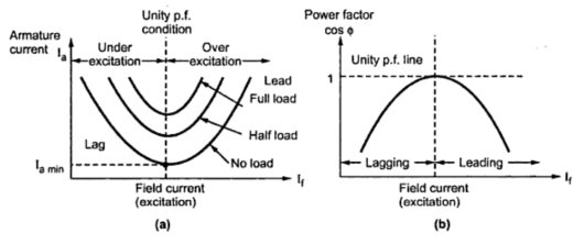
it is clear that if excitation is varied from very low (under excitation) to very high (over excitation) value, then current Ia decreases, becomes minimum at unity p.f. and then again increases. But initial lagging current becomes unity and then becomes leading in nature. This can be shown as in the Fig. 1.
 |
| Fig. 1 |
Excitation can be increased by increasing the field current passing through the field winding of synchronous motor. If graph of armature current drawn by the motor (Ia) against field current (If) is plotted, then its shape looks like an english alphabet V. If such graphs are obtained at various load conditions we get family of curves, all looking like V. Such curves are called V-curves of synchronous motor. These are shown in the Fig. 2a).
As against this, if the power factor (cos Φ) is plotted against field current (If), then the shape of the graph looks like an inverted V. Such curves obtained by plotting p.f. against If, at various load conditions are called Inverted V-curves of synchronous motor. These curves are shown in the Fig. 2(b).
 |
| Fig. 2 V-curves and Inverted V-curves |
1.1 Experimental Setup to Obtain V-Curves
Fig. 3 shows an experimental setup to obtain V-curves and Inverted V-curves of synchronous motor.
Stator is connected top three phase supply through wattmeters and ammeter. The two wattmeter method is used to measure input power of motor. The ammeter is reading line current which is same as armature (stator) current. Voltmeter is reading line voltage.
 |
| Fig. 3 Experimental setup for V-curves |
A rheostat in a potential divider arrangement is used in the field circuit. By controlling the voltage by rheostat, the field current can be changed. Hence motor can be subjected to variable excitation condition to note down the readings.
Observation Table :

Now IL = Ia, per phase value can be determined, from the stator winding connections.
IL = Iaph for stator connection
IL/√3 = Iaph for delta connection
The power factor can be obtained as

The result table can be prepared as :

The graph can be plotted from this result table.
1) Ia Vs If → V-curve
2) cosΦ Vs If → Inverted V-curve
The entire procedure can be repeated for various load conditions to obtain family of V-curves and Inverted V-curves.
Subscribe to:
Posts (Atom)